BACKGROUND
A Cooling, filling/packing and warpage analysis was conducted on Family Moldy The product has been analyzed to Evaluate the gating locations suggested and proposing optimized gate(balanced) , filling properties, analyze shear stress, shear rates, flow front temperatures, position of weld line, air trap, sink mark etc
The material suggested was PA 66 30% GF. This material has been taken from Mold Flow’s database after being tested for Viscosity, PVT & Thermal Data in the Mold flow laboratory
OBJECTIVES
To evaluate product design and gate placement to achieve a uniform filling of the cavity with optimized wall sections as well as reducing stress levels of the component during filling to acceptable levels.
To design and optimize runner and gate system.
To optimize the processing conditions in order to help maintain flow front temperature and reduce both shear rate and shear stress levels.
To achieve uniform filling and balanced fill of the cavity with regard to over pack, under pack and weld line positions.
To achieve a wide molding process window for the optimization of production quality components.
To report on problems associated with the product and tool design and offer solutions.
To predict warpage in the X, Y, Z plane and optimize to achieve minimal distortions.
To suggest solution of findings.
MOLDING CONDITIONS
Cycle Breakdown
| Descriptions | Proposed | Actual |
| Specified Injection Time | 2 sec | |
| Actual Injection Time | 2.55sec | |
| Total Packing Time | 8 sec | |
| Total Cooling Time | 20 sec |
Filling Parameters
| Descriptions | Proposed | Actual |
| Melt Temperature | 275 deg. C | |
| Mold Temperature | 90 deg. C | |
| Maximum Injection Pressure (during fill) | 117 MPa | |
| Maximum Clamp Force (during filling) | 156 tones |
Packing Parameters
| Descriptions | Proposed | Actual |
| Maximum Clamp Force (during Packing) | 230 tones | |
| Switch Over (speed to pr) | 98% of Vol. |
Part Parameters
| Descriptions | Proposed | Actual |
| Shot Volume (Aprox.) | 155 cu.cm |
Material Data
| Material | PA 66 30% GF |
| Material Recommended Melt Temperature | 275deg.C |
| Material Recommended Mold Temperature | 90 deg.C |
| Material Recommended Maximum Shear Stress | 0.5MPa |
| Material Recommended Maximum Shear Rate | 60000 1/s |
Considerations
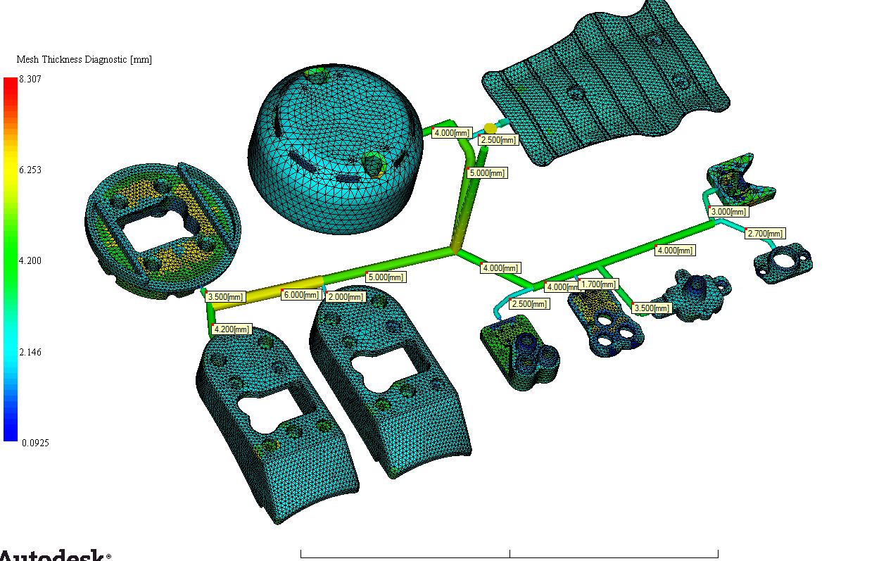
The Feed System Consideration For Balanced Filling is Shown below
Gate Location as per tool lay-out.
The Results are as:-
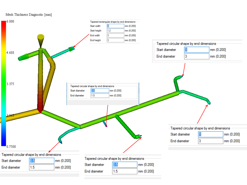
Considerations
The gate openings for fill balancing
The Results are as:-

Considerations
The gate openings for fill balancing
The Results are as:-
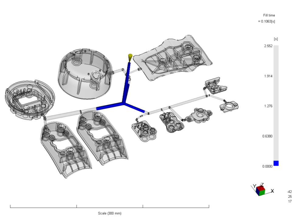
Fill Time
Initial Fill Time assumed was 2 sec (Assuming flow rate of 70cc/s) with the software estimated fill time of 2.5 sec. 93% Fill balance is achieved by adjusting the runner and gate.
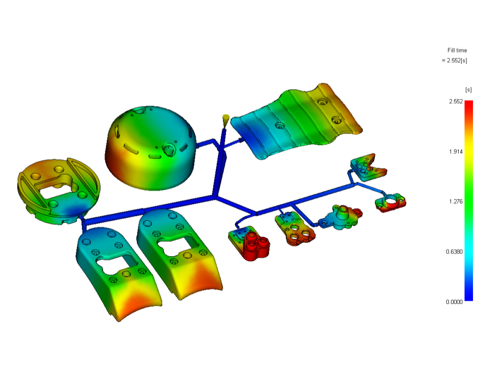
Fill Time
Initial Fill Time assumed was 2 sec (Assuming flow rate of 70cc/s) with the software estimated fill time of 2.5 sec. 93% Fill balance is achieved by adjusting the runner and gate.
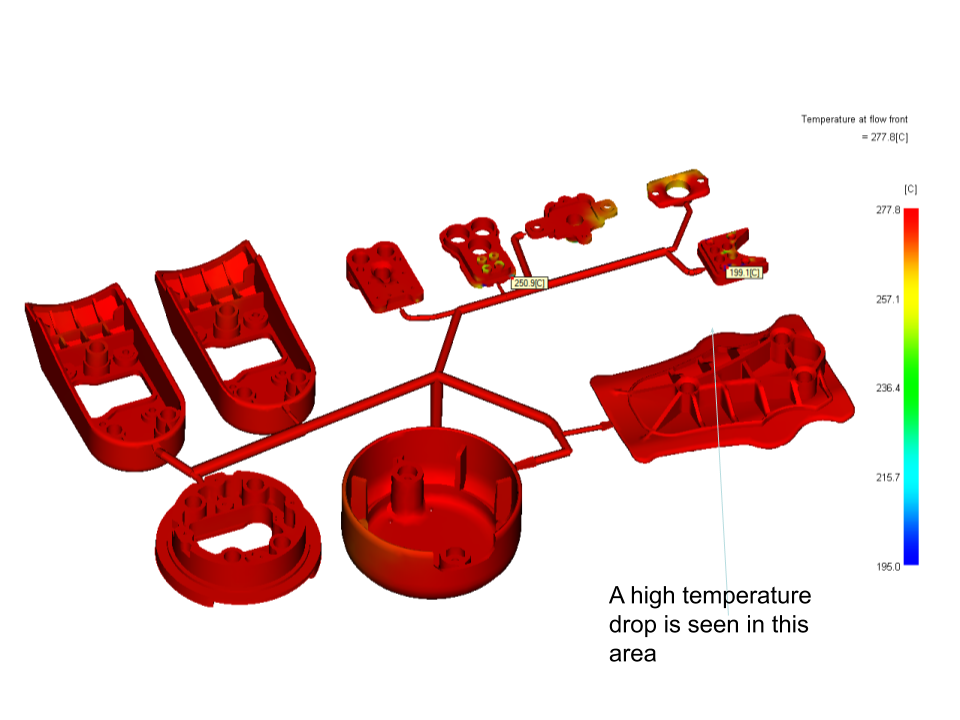
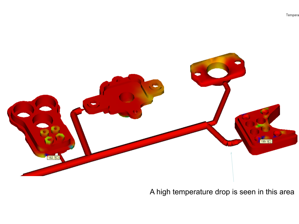
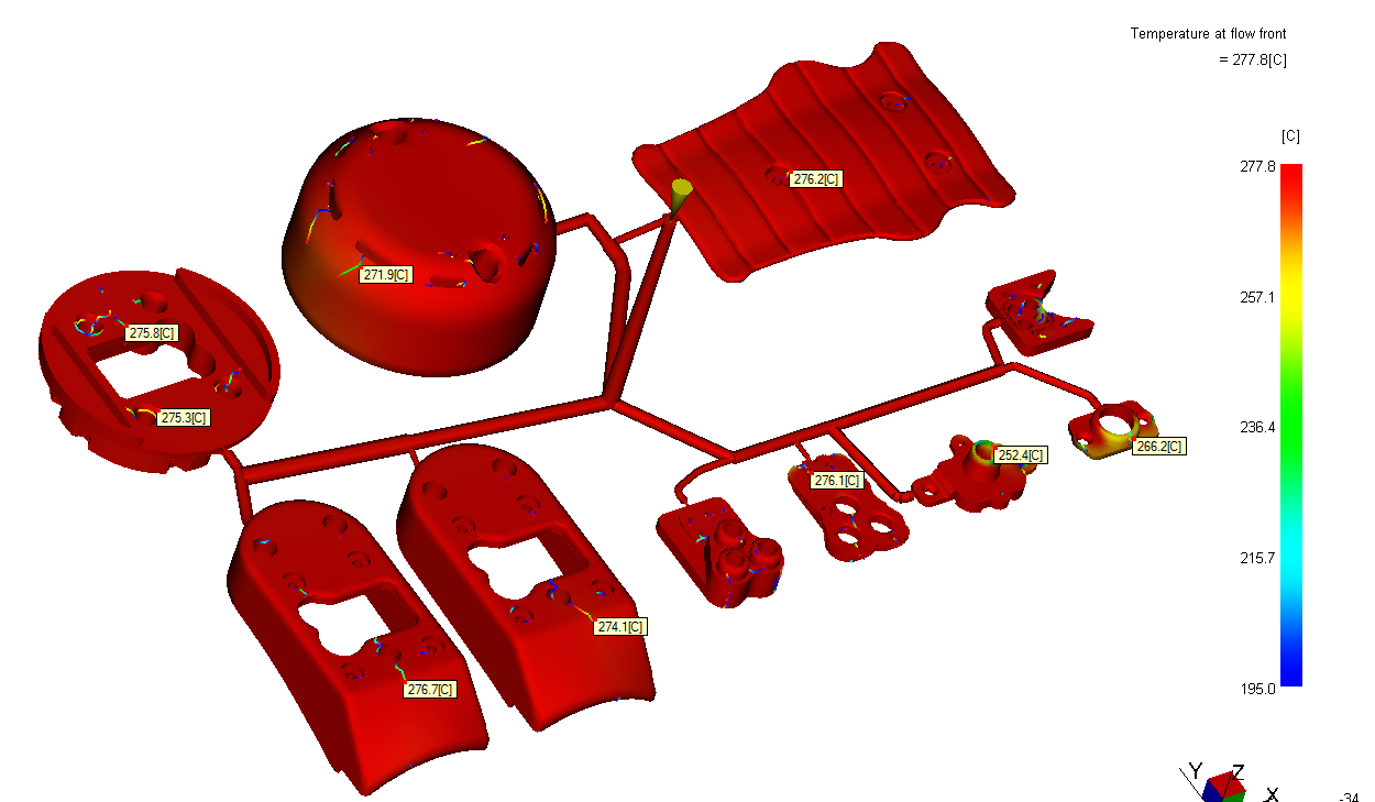
Temperature Flow Front
Plot displays the flow front temperature distribution. Temperature variation is within ±8.5°C except one part. This is considered as a good scenario and should maintain excellent weld line strength & provide moulder wide moulding window to fine tune parameters
Temperature Flow Front
Plot displays the flow front temperature distribution. Temperature variation is within ±8.5°C except one part. This is considered as a good scenario and should maintain excellent weld line strength & provide moulder wide moulding window to fine tune parameters
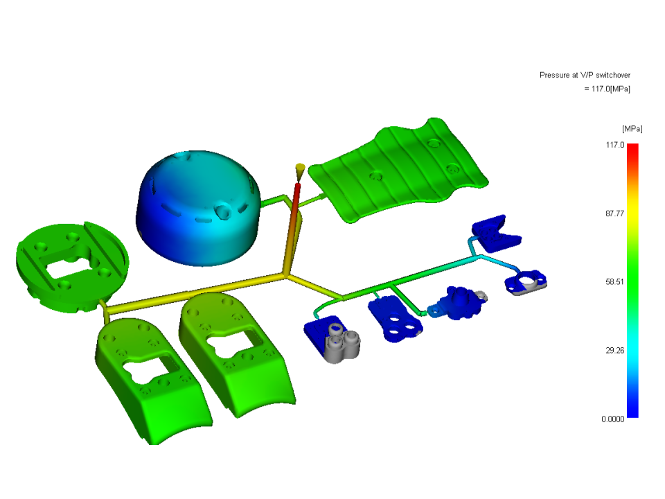
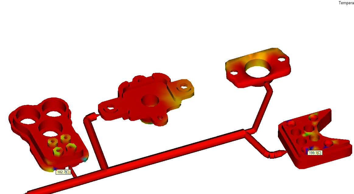
Pressure
Pressures required to fill this component is 117 MPa. This is considered as high considering wall section variation, flow length & raw materials.
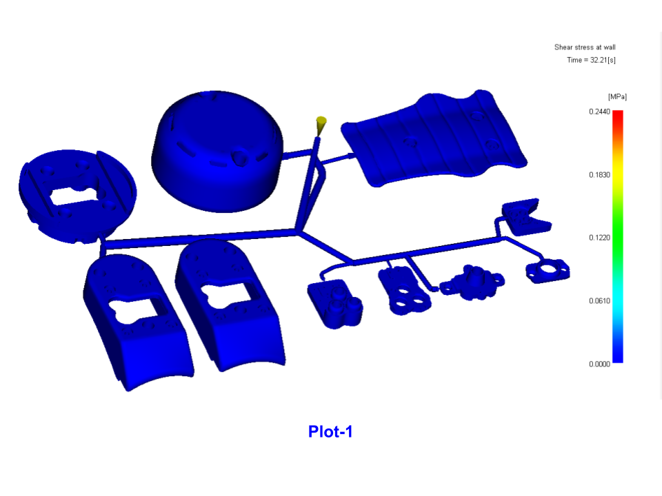
Shear Stress
Plot shows Shear Stress distribution in the part. This is evident from plot-1 majority of component area is within specified limit of 0.5 MPa.
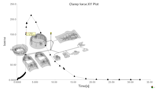
Clamp Force
Clamp force at switch over is 156 tonnes
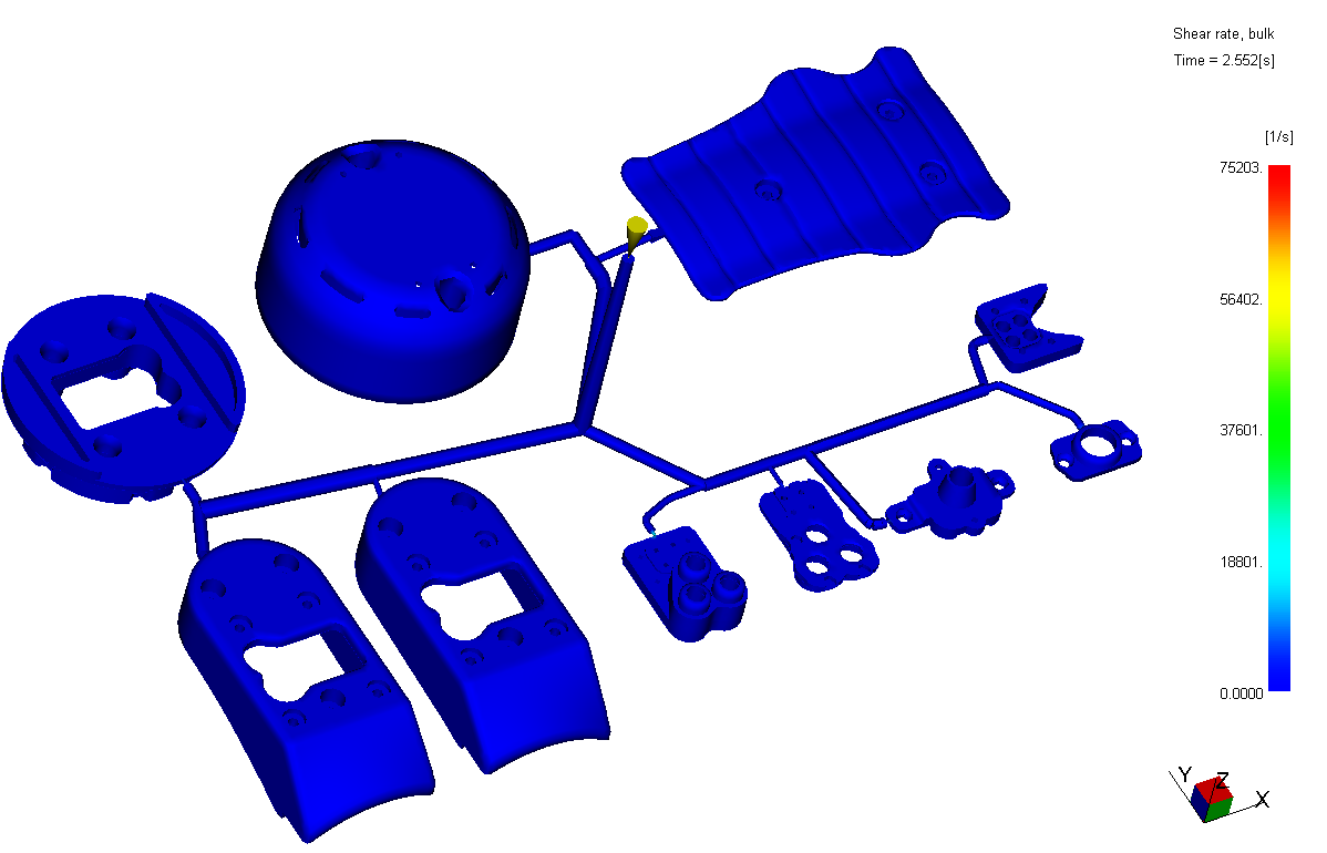
Shear Rate
Plot shows Shear rate distribution in the part. Component area is well below suppliers recommended limit 75203 l/s this is evident from plot. Gate region is less than specified limit of 60000 1/s for all gates. Local shear heating observed in gate
Weld Lines
Plots display the location of weld line. These are all meld lines considering temperature and pressure at these points, so strength will be good, which will not be visible.
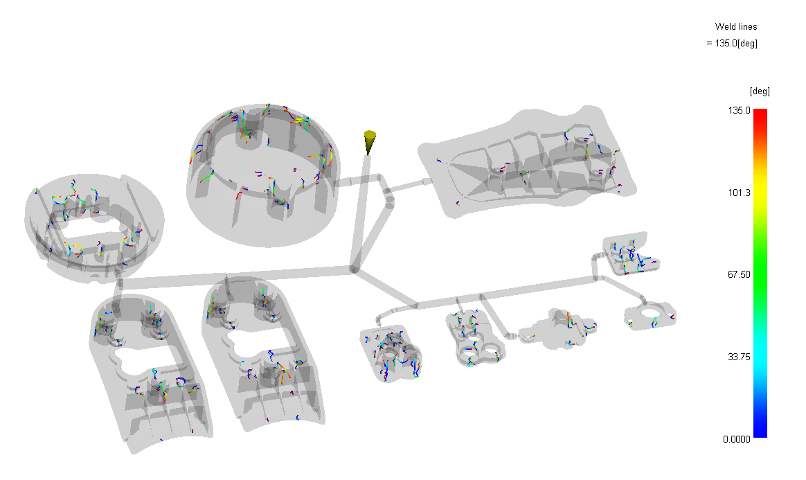
Weld Lines Overlaid with Temperature Plot
Plots display the location of weld line. These are all meld lines considering temperature and pressure at these points, so strength will be good, which will not be visible.
Weld Lines Overlaid with Temperature Plot
Plots display the location of weld line. These are all meld lines considering temperature and pressure at these points, so strength will be good, which will not be visible.
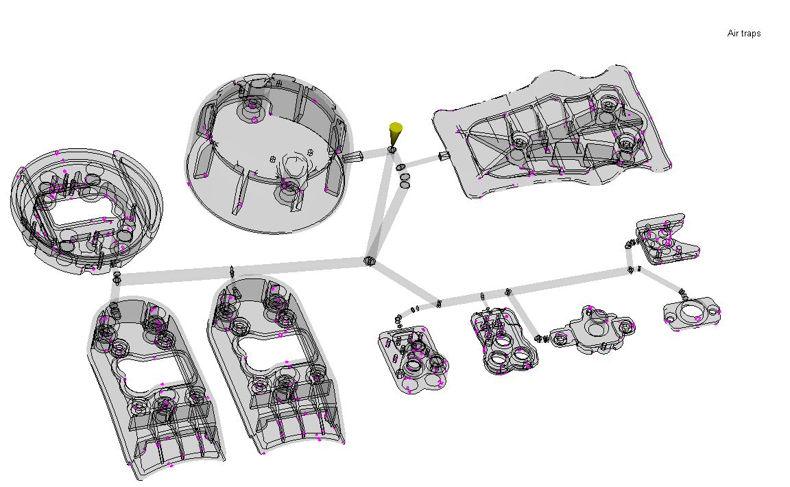
Air Traps
These plots display the location of possible air entrapment areas. All entrapments should be taken into account by the toolmaker, where proper venting is suggested. Insufficient venting may result in high injection pressure.
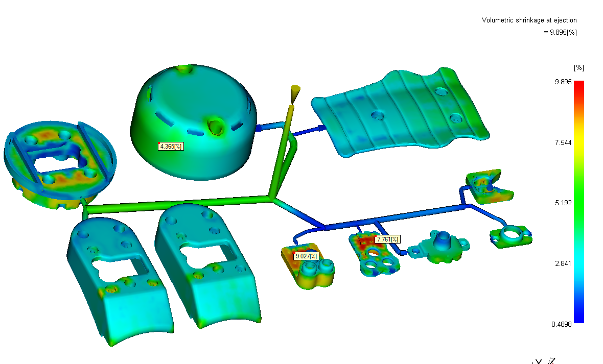
Volumetric Shrinkage at ejection
Plot shows almost uniform volumetric shrinkage from 0.4 to 9.8%. Higher Shrinkage is observed where thickness is higher.
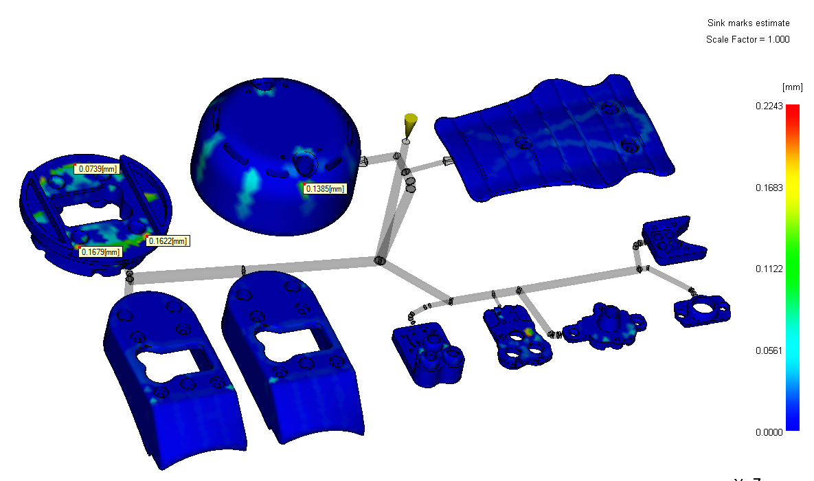
Sink Mark
By filling this component on higher clamp tonnage machine no sink mark will evident with thickness. By applying proper packing profile possibility of sink mark can be avoided.
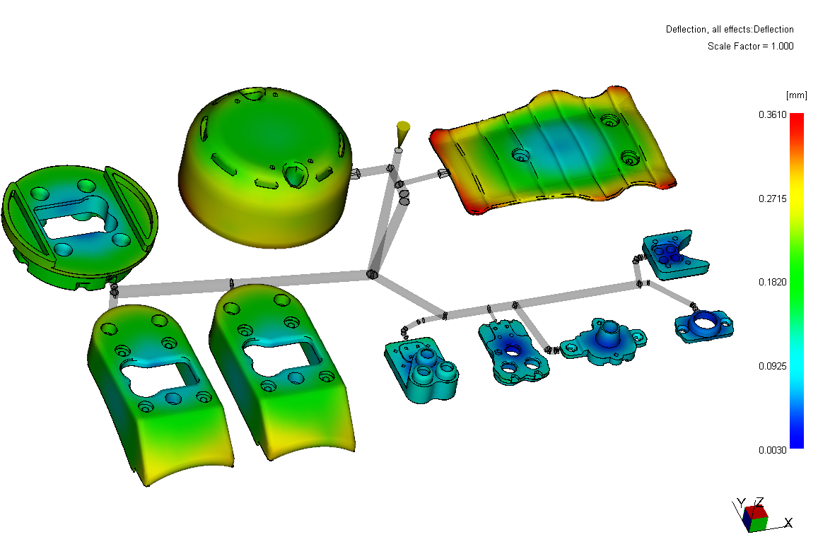
Deflection Plots
Deflection Total
This print displays total deflection in the part in all directions.
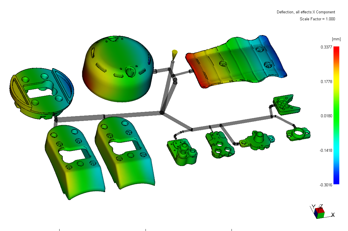
Deflection X
This print displays deflection in the X direction within the product.
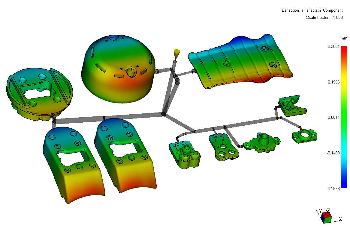
Deflection Y
This print displays deflection in the Y direction within the product.
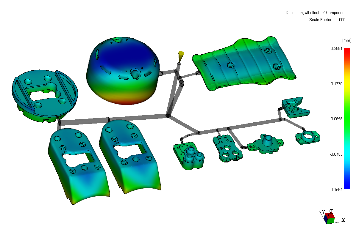
Deflection Z
This print displays deflection in the Z direction within the product.
Conclusions
We have performed several filling and warpage analysis on the family mold .The aim of the Analysis was to have a set of processing conditions that would enable a large molding window to be obtained, thereby allowing variations to the molding parameters for the quality aspects of the part and analyzing characteristics of the product to achieve balancing in Fill. The following facts can be concluded.
- The flow Analysis of part showed no major problems during filling using specified material and showed 93% balancing in fill after changing the runner and gate dimension.
- Pressure requirement is 117 MPa. This is considered as good considering wall section variation, flow length & raw materials.
- The Flow Front temperature has 8.5°C variation over majority of components, which is considered as a very good scenario and should maintain excellent weld line strength & provide moulder wide moulding window to fine tune parameters.
- Shear stresses are within specified limit in majority of component area. Some elements area above specified limit which would not affect part quality.
- Provision should be made in the tool for venting as shown in plots. This is to be noted by tool maker.
- Meld lines formed due to flow merging and noted by tool maker to provide air vents in that location.
- Clamp tonnage required to fill this part is 156 tones
- No sink mark observed on filling 300 tones machine. To minimize sink mark depth.
Suggestions
- Incorporate air vents in tool as shown location in plots. Care will need to be taken by tool designer to incorporate either vent pins or ejectors in these areas to allow proper venting